
Resistivity Method – The Basics
Without going into the physics of Ohm’s law, if you run a current through different materials you can calculate the electrical resistance by measuring the voltage and current applied. In practice this means that a resistivity survey will form an electrical circuit through the ground and take voltage and current measurements to calculate the resistivity of the sub-surface rocks.
For mineral exploration, resistivity surveys offer another indirect method to assist mapping and understanding the sub-surface geology, before we spend serious money on a drilling programme.
Alternative Geophysical Surveys:
Why Do A Resistivity Survey?
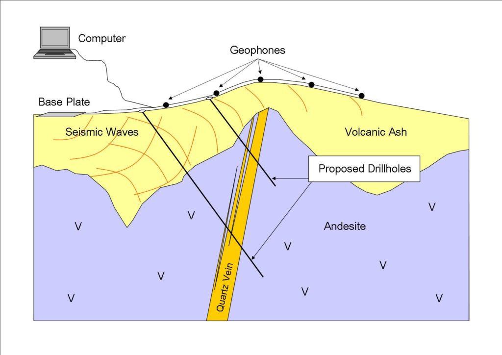
The resistivity of the subsurface varies depending on rock type, porosity, permeability, the amount and type of salts present in the ground water and the type of clay present. When resistivity is low, conductivity is correspondingly high. Therefore, the method is useful for locating massive sulphide deposits and graphite-rich zones, both of which conduct electricity. When exploring for epithermal gold deposits the presence of quartz-rich zones and veins is important. Quartz, the most common mineral in epithermal veins and associated breccia, has a very high resistivity relative to other minerals. For this reason, quartz-rich zones that may host gold mineralisation , show up in surveys as zones of high resistivity or low conductivity.
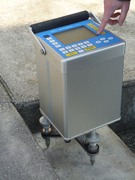
How Is a Resistivity Survey Done in the Field?
An electrical resistivity survey involves laying out a series of electrodes, each driven into the ground about 150 millimetres. Their spacing is dependent on the depth of penetration required. The further apart the electrodes, the deeper the resistivity measurements of the subsurface that can be taken. Typically resistivity surveys range in depth from a few metres to more than 100 metres. The disadvantage of trying to obtain measurements from greater depths is a resultant loss in resolution.
There are number of possible layouts for electrodes; the Wenner and Schlumberger arrays are the most common. The Wenner array is the simplest, having an equal spacing between the electrodes. In the Schlumberger array, the spacing between the current electrodes is greater than the spacing between the voltage electrodes. Other configurations include the dipole-dipole and pole-dipole arrays.

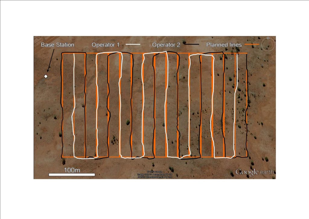
A resistivity survey may consist of a single line profile across a point of interest. Alternatively, readings are taken in a grid pattern to obtain a three-dimensional image of the subsurface resistivity. A grid survey requires either advancing the electrodes along a given line or by having a number of arrays connected along a line with data simultaneously collected and recorded by the instrumentation.
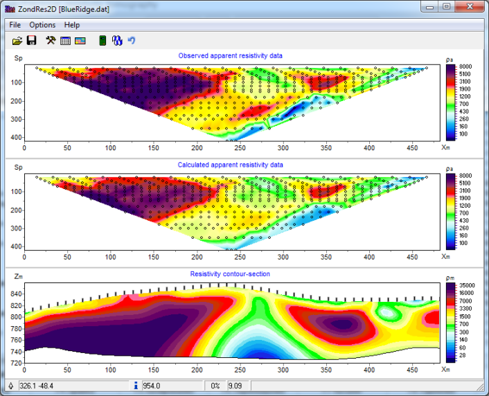
The normal result of a resistivity survey is a number of profiles that show the variation in resistivity with depth. These profiles are examined and interpreted by a geologist who locates targets for follow-up exploration.
Induced Polarisation (IP) Method
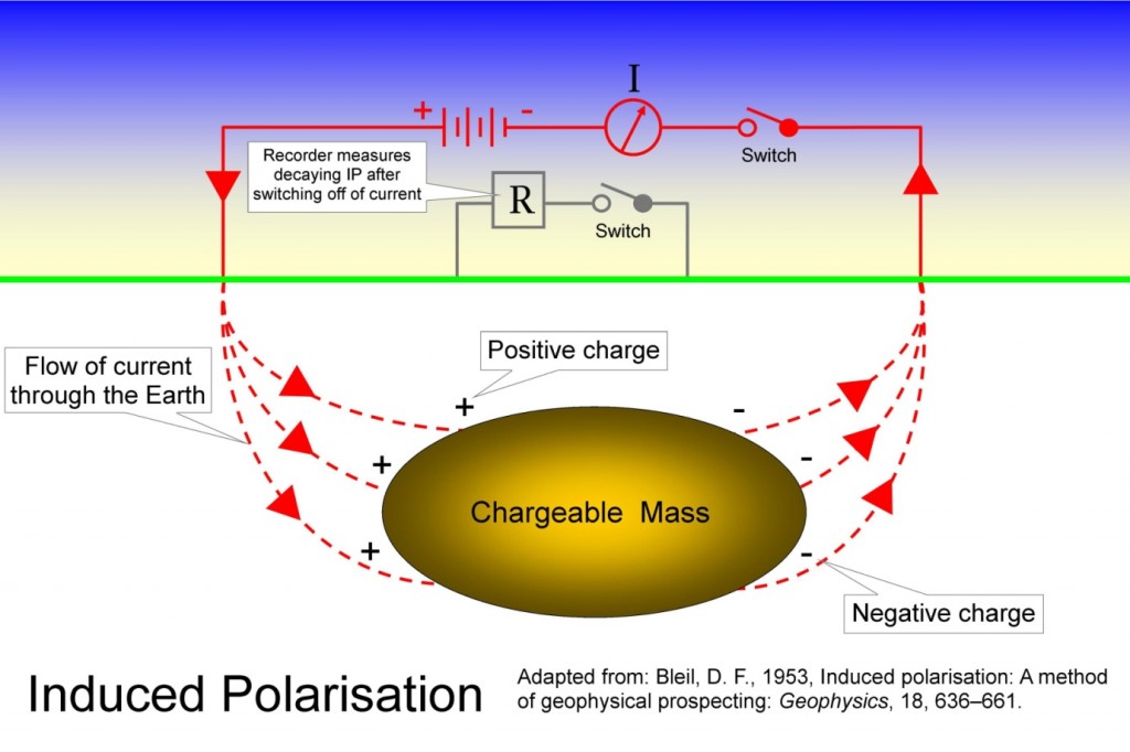
When an electrical current is applied to some materials a phenomenon known as “induced polarisation (IP)” occurs, with a charge being acquired. When the current is switched off the charge dissipates over time, in a similar way that a car’s battery slowly goes flat if the car is not regularly used.
An induced polarisation survey is usually run at the same time as a resistivity survey. The resistivity method can be adapted to an induced polarisation method with the addition of switches and changes to the instrumentation. One of the main advantages of doing the two types of surveys together is to save time as well as associated costs.
The collection of induced polarisation data involves measuring the voltage at certain times after the current is switched off, usually over a period of a few seconds. There are two switches in the layout. The switch on the recorder part of the circuit, which measures the decaying voltage, is left open until the moment the current is switched off.
Different materials have different IP responses. Disseminated or dispersed sulphide grains within a large body of rock, for example porphyry and strataform deposits usually have a strong IP response. Small semi-massive sulphide bodies generally have a weak IP response. In gold exploration, associated minerals such as pyrite and arsenopyrite may be present in sufficient quantity in the neighbouring rock to cause an IP effect. Therefore gold mineralisation may be indirectly detected using the IP method.